

Product type
 Contact Information
+86 755 89660635
+86 189 2461 3736

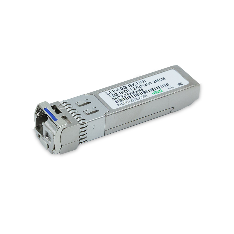
10GBASE SFP+ BiDi 1270nm-TX/1330nm-RX 20km LC DDM SMF Optical Transceiver Module
ZK-SFP+-BX20
10Gbps SFP+ BIDI 20km SMF Transceiver
Features
n SFP+ package with LC connector
n 1270nm(1330nm) DFB Laser and PIN-TIA photodetector
n Up to 20Km transmission on SMF
n Up to 11.3Gbps Data Links
n Support dual CDR in TX and RX channel(optional)
n +3.3V single power supply
n Power dissipation<1.5W
n 2-wire interface with integrated Digital Diagnostic monitoring
n Low EMI and excellent ESD protection
n laser safety standard IEC-60825 compliant
n Compatible with RoHS
n Compliant with SFF-8472 SFP+ MSA
n Compliant to SFP+ SFF-8431 and SFF-8432
Applications
n 10GBASE-LR/LW 10G Ethernet
n 1200-SM-LL-L 10G Fibre Channel
Description
ZK-SFP+-BX20 are designed for Single Fiber Bidirectional serial optical data communications up to 11.3 Gb/s.The electrical interface is compliant with SFI specifications of SFF-8431. The transceiver consists of 10Gbit/s1330nm DFB optical transmitter and PIN receiver, and transmission distance up to 20km on 9/125µm singlemode fiber.
Absolute Maximum Ratings
Parameter | Symbol | Min. | Typ. | Max. | Unit | Note |
Storage Temperature | Tst | -40 | +85 | °C | ||
Supply Voltage | Vcc | -0.3 | +4.0 | V | ||
Operating Relative Humidity | RH | 5 | 95 | % |
Recommended Operating Conditions
Parameter | Symbol | Min. | Typ. | Max. | Unit | Note |
Operating Case Temperature | Tcase | 0 | 70 | ºC | ||
Power Supply Voltage | VCC3 | 3.135 | 3.3 | 3.465 | V | |
ICC3 | - | - | 230 | mA | ||
Power Dissipation | PD
| - | - | 0.8 | W | |
Data Rate | Gb/s | 2.4576 | 10.3125 | 11.3 | Gbps | |
Transmission Distance | - | - | 20 | km |
Optical Characteristics
Parameter | Symbol | Min. | Typ. | Max. | Units | |
Transmitter | ||||||
Center Wavelength | Tx 1270 | lo | 1260 | 1270 | 1280 | nm |
Tx 1330 | 1320 | 1330 | 1340 | |||
Spectral Width(-20dB) | Tx 1270 | Dl | 1 | nm | ||
Tx 1330 | 1 | |||||
Average Output Power | Tx 1270 | Po | -5 | 0 | dBm | |
Tx 1330 | -5 | 0 | ||||
Extinction Ratio | Er | 3.5 | dB | |||
Side-Mode Suppression Ratio | SMSR | 30 | dB | |||
Total jitter | Tj | IEEE 802.3ae | ||||
Receiver | ||||||
Center Wavelength | Rx 1330 | lo | 1320 | 1330 | 1340 | nm |
Rx 1270 | 1260 | 1270 | 1280 | |||
Receiver Sensitivity | Rsen | -13 | dBm | |||
Receiver Overload | Rov | -3 | dBm | |||
Return Loss | 12 | dB | ||||
LOS Assert | LOSA | -25 | dBm | |||
LOS Dessert | LOSD | -14 | dBm | |||
LOS Hysteresis | 0.5 | 4 | ||||
Electrical Interface Characteristics
Parameter | Symbol | Min. | Typ. | Max. | unit | |
Transmitter | ||||||
Input Differential Impendence | Zin | 90 | 100 | 110 | Ohm | |
Data Input Swing Differential | Vin | 180 | 700 | mV | ||
TX Disable | Disable | 2.0 | Vcc | V | ||
Enable | -0.3 | 0.8 | V | |||
TX Fault | Assert | 2.4 | Vcc | V | ||
Deassert | -0.3 | 0.8 | V | |||
Receiver | ||||||
Output differential impendence | Zout | 80 | 100 | 120 | Ohm | |
Data Input Swing Differential | Vout | 300 | 850 | mV | ||
Rx_LOS | Assert | 2.0 | Vcc | V | ||
Deassert | -0.3 | 0.4 | V | |||
Pin Description

Pin | Logic | Symbol | Name/Description | Note |
1 | VeeT | Module Transmitter Ground | 1 | |
2 | LVTTL-O | TX_Fault | Module Transmitter Fault | 2 |
3 | LVTTL-I | TX_Disable | Transmitter Disable; Turns off transmitter laser output | 3 |
4 | LVTTL-I/O | SDA | 2-wire Serial Interface Data Line (Same as MOD-DEF2 as defined in the INF-8074i) | 4 |
5 | LVTTL-I/O | SCL | 2-wire Serial Interface Clock (Same as MOD-DEF1 as defined in the INF-8074i) | 4 |
6 | MOD_ABS | Module Absent, connected to VeeT or VeeR in the module | 5 | |
7 | LVTTL-I | RS0 | Not used | |
8 | LVTTL-O | RX_LOS | Receiver Loss of Signal Indication (In FC designated as RX_LOS, in SONET designated as LOS, and in Ethernet designated at Signal Detect) | 2 |
9 | LVTTL-I | RS1 | Not used | |
10 | VeeR | Module Receiver Ground | 1 | |
11 | VeeR | Module Receiver Ground | 1 | |
12 | CML-O | RD- | Receiver Inverted Data Output | |
13 | CML-O | RD+ | Receiver Non-Inverted Data Output | |
14 | VeeR | Module Receiver Ground | 1 | |
15 | VccR | Module Receiver 3.3 V Supply | ||
16 | VccT | Module Transmitter 3.3 V Supply | ||
17 | VeeT | Module Transmitter Ground | 1 | |
18 | CML-I | TD+ | Transmitter Non-Inverted Data Input | |
19 | CML-I | TD- | Transmitter Inverted Data Input | |
20 | VeeT | Module Transmitter Ground | 1 |
Notes:
1.The module signal ground pins, VeeR and VeeT, shall be isolated from the module case.
2.This pin is an open collector/drain output pin and shall be pulled up with 4.7k-10kohms to Host_Vcc on the host board. Pull ups can be connected to multiple power supplies, however the host board design shall ensure that no module pin has voltage exceeding module VccT/R + 0.5 V.
3.This pin is an open collector/drain input pin and shall be pulled up with 4.7k-10kohms to VccT in the module.
4.See SFF-8431 4.2 2-wire Electrical Specifications.
5.This pin shall be pulled up with 4.7k-10kohms to Host_Vcc on the host board
Recommended Interface Circuit

Mechanical Dimensions
Important Notice
Performance figures, data and any illustrative material provided in this data sheet are typical and must be specifically confirmed in writing by Zkosemi before they become applicable to any particular order or contract. In accordance with the Zkosemi policy of continuous improvement specifications may change without notice. The publication of information in this data sheet does not imply freedom from patent or other protective rights of Zkosemi or others. Further details are available from any Zkosemi sales representative.